Introduction
The device is delivered ready for use and will only need 10-32 VDC to operate. Seamless roaming ensures that the gateway always connects to the best available cellular network. The gateway comes with a power supply for indoor use. However, the gateway is water resistant (IP67) and can be mounted in wet areas together with PN 422336 Neuron PSU (IP67) or by the use of PN 422339 Neuron Power Cable (IP67).
Mounting the Gateway
To ensure the best possible signal strength and minimize interference, it is important to mount the gateway with some distance to fixed objects. This applies to all sides of the gateway, including the back of the unit. A clearance of at least 5 cm between the wall and the gateway should be maintained to achieve optimal coverage. This can be achieved using PN 422335 Gateway Mounting Kit, or other methods that create the necessary space (see picture below).
It is also important to place the gateway high up, as this normally results in fewer physical obstacles in the surrounding environment.
Sources of Interference to Avoid: To guarantee reliable wireless communication, do not mount the gateway in close proximity to major noise sources or signal blockers. Maintain as much distance as possible to:
Large metal surfaces: Avoid mounting directly onto steel plates, metal cabinets, or reinforced concrete structures, as these reflect and degrade the radio signals.
High-power electrical equipment: Keep a safe distance from frequency converters (VFDs), heavy electric motors, and welding equipment.
Power cabling: Do not route or place the gateway directly alongside high-voltage or three-phase power cables.
Other wireless transmitters: Avoid placing the unit immediately next to high-power Wi-Fi access points or other radio equipment.
Note: Remember to position the equipment so that it is not difficult to disconnect the power supply if necessary.
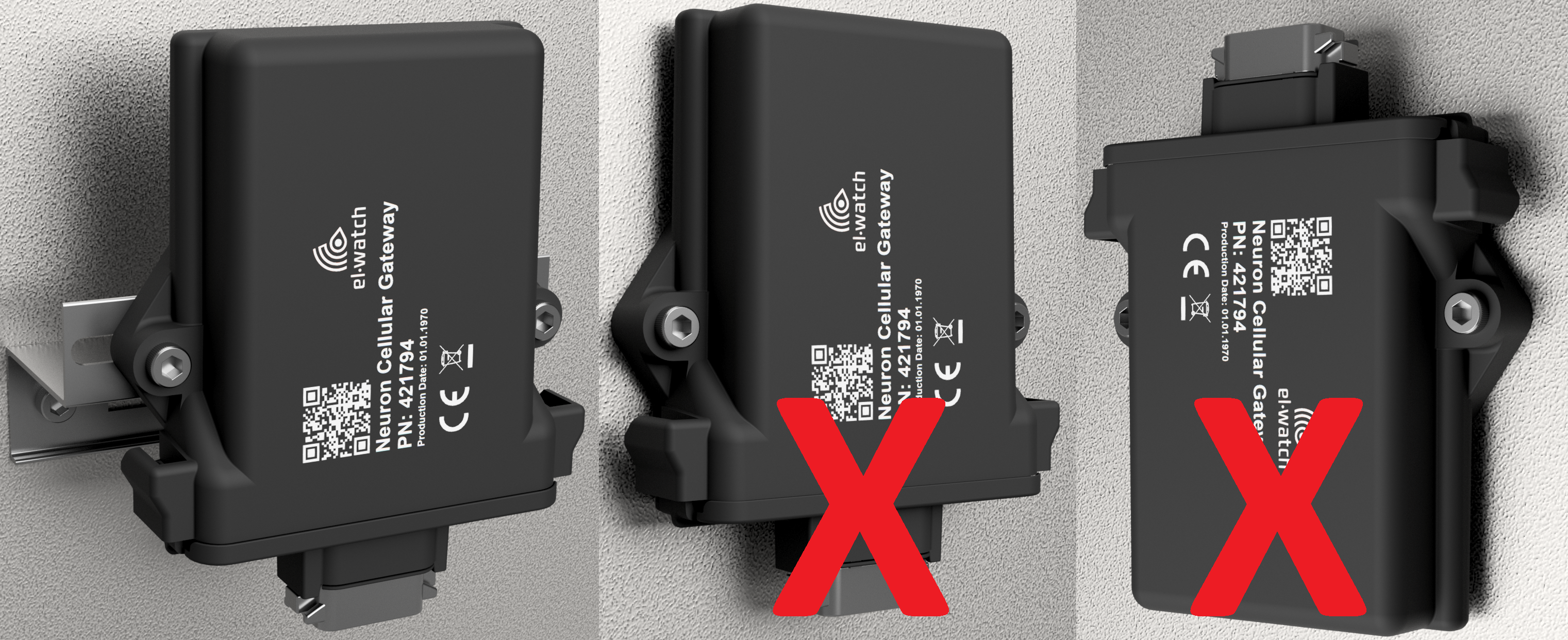
Connect the power plug (from the Neuron PSU or Neuron Power Cable) to the power inlet on the gateway. The power inlet is the lower part of the gateway in the picture on the left above.
Accessories
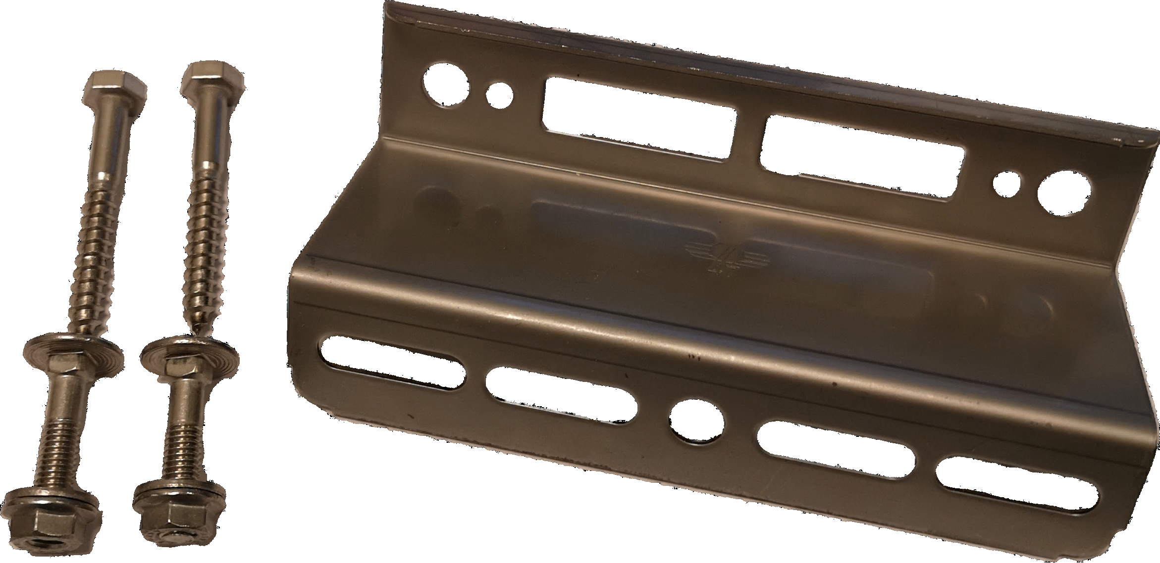 PN 422335 Neuron Cellular Gateway Mounting kit
.png) PN 422336 Neuron PSU for Cellular Gateway. IP67 PSU
PN 422336 Neuron PSU for Cellular Gateway. IP67 PSU
.png) PN 422339 Neuron Power Cable for Cellular Gateway. IP67 rated, 14m long power cable for connecting gateway to existing power supplies
PN 422339 Neuron Power Cable for Cellular Gateway. IP67 rated, 14m long power cable for connecting gateway to existing power supplies